So why have I, or indeed any boaters got a generator? I think in most cases 99% + its to charge our batteries. Of course we all have one bolted to the side of our main engine which by and large does an excellent job of charging the start battery for which it was designed for and a pretty fair to poor job of charging supplementary or house batteries via various methods of diverting surplus charge elsewhere.
When I did my alternator conversion the one thing I didn't expect to be as successful as it has proved was the ability to run my oven 2.2kw through the inverter and still be putting in as required depending on the SOC of the batteries up to 60amps of charge. This set me thinking, why the hell am I making 230v to run my inverter charger to then charge the batteries at a maximum of 120amps when my new alternator on the main engine I have seen putting in over 180amps without conversion losses. I have read somewhere that the Victron inverter on charge makes 800w of heat as well. Heat I really don't want. This I can well believe as I had to add additional fans to the inverter space under the stern steps in order to keep it cool enough to keep the charge rate up as it shuts down the charge rate according to the running temperature. I checked the temperature of the inverter before I installed the extra fans and it showed a surprising 45c.
So you might wonder where this is leading. Well as I see it its simple. Use my current 500cc genset engine to spin a 12v alternator instead of running a 4000cc (4L) to do the same. Big engines like this suffer from bore glazing running on tick over or low loads. Google bore glazing its an interesting topic with many views generally eventually agreeing its not a good thing. But would my current engine be powerful enough?
So is the 12hp engine powerful enough?
This would be the maximum output. It's very unlikely my batteries could ever draw this much. The plan is to run the engine at 1500rpm, however it can be run faster if needed. Why 1500? well its very quiet at that rpm, but even at 2000rpm its a fraction of the noise at 3000rpm.
This is the horsepower required to achieve this.
This is what I am looking to achieve at 1500rpm
This is the horsepower required.
These calculations are of course in ideal situations with a new engine, however there is still about 33% to play with.
So time will tell, but I'm confident the engine will drive it. Interestingly when I was considering a 1500rpm 4 pole 230v alternator it was calculated by the intended supplier that it could not exceed 3kw output.
My initial research lead me to a 220amp automotive alternator but this would need spinning at 5000+rpm so gearing would be required. I had considered running a 3kw 230v alternator at 1500rpm (4 pole) but again this still had the electrical conversion losses but in preparation for this I managed to con my current genset into running at 1500rpm by removing a slow run cutout relay. At 1500rpm its as quiet as a sewing machine. But then I will need to have made for me a drive pulley set and this will have additional frictional losses and belt slip reducing the limited power the genset engine has.
So having bought the 220amp automotive unit
220amp Automotive alternator
I did some more Googling and found a slow speed 12v alternator from the USA.
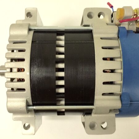
The Ecoair company make exactly what I and every boat owner needs, and a 24v version also.
325amp Slow spin alternator
So having stripped my current genset:-
Vetus genset with cocoon
The 230v armature still to be removed
Armature and coupling removed
Flywheel end of the engine
Armature and coupling removed
Flywheel end of the engine
This was a 6 hole fixing with 200mm PCD so I looked up the SAE of this fixing which was 6 1/2J.
Its big! and it's heavy 18kg!
In the interim I had been looking at drive options. I decided to make a new drive plate:-
to which I will probably use a Fenner HRC Coupling or possibly a Fenner Tyre Coupling.
Old drive plate
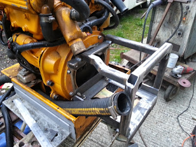
This is the new frame I have made to do 2 jobs. 1st job is to support the rear of the engine. Previously the 230v alternator body did this. The new 12v alternator isn't designed to do this
This doesn't look much but it took several hours of head scratching and trying different things. There was 2 main problems / considerations in the design. The 1st and most important was to maintain all the original parts so it could be put back to original. 2nd, I wanted it all to fit back in the original sound reducing box. The other minor problems were to ensure access and use all the original bolts and the exhaust pipe route got in the way. The final consideration was to ensure the new alternator could be fitted and removed as the pad mount lugs are wider than the diameter of the main body.
The pads of the alternator sits flat on top of the flats of angle irons and bolted through
The new drive plate has been made and fitted.
Once the drive plate and new support frame was fully bolted into place a final dial gauge test was done. On the end of the shaft there was 5/1000th of an inch run out. This shaft will be cut back on final assembly to about 11/4" (30mm) when the HRC90 coupling is fitted. This will reduce the run out even more. The coupling is designed to take way more run out than this.
This video explains better than I ever could how the taper lock system works.
With the new drive plate fitted and the shaft length reduced to about 50mm
I connected the coupling halves to the the stub and the alternator.
Having previously marked out and drilled the mounts for the alternator
these were bolted on. I chose to use captive nuts to make removal easier as access the underside is limited.
This new assembly was then slid into place and the alignment carefully undertaken.
Once I was happy with the alignment the supports were clamped in place and the alternator removed to permit welding.
I could have welded it without removing the alternator but when working on this it has to be remembered that it is a permanent magnet alternator and therefore any welding or grinding will make fine steel particles which could be drawn on the the magnets and cause problems. All such work was undertaken with the alternator out of the way.
Once I was satisfied everything was tight it was time for the first start up. Once the engine was up to working temperature I set it to run at it target speed of 1500rpm
a car battery was connected with jump leads to the alternator and a voltage reading taken.
The regulator is set for 14.8v so this was pretty spot on.
Once the cocoon was re-fitted and the control panel put back and a new power outlet board made with 2 x 10mm brass bolts. A new hour meter running on 12v was fitted, the old one was 240v
The genset is now in back in the boat connected to the batteries with 95sq/mm cabling and is undergoing tests. Initial results are very good. I let my battery bank go down to 86% SOC. On starting the genset the initial charge rate was 184 amps at 13.8v the batteries quickly charged (1.5 hours or so) to 95% with a reading still of 106 amps at 14.2v. The remaining 5% took another hour or so when the charge had dropped to 54amps at 14.4v
If this same charge had been done with the 240v feeding the Victron charger the time would have been well over 5 hours with the generator running at 3000rpm. The 12v charge was done at 1800rpm in the end. 1500rpm was the target but it was a bit lumpy with the heavier load on it. 1800rpm was a nice sweet spot.
The following day I did a similar charge to 88% - 95% and curiously the batteries charged faster at just a little over an hour. Also I've noticed the resting battery voltage is holding up higher for longer. It seems the batteries are charging better already.


It hurt just looking at your finger, glad to hear it will all reconnect. :)
ReplyDeleteLook's like a very good job on the generator.
Bill Kelleher
Bloody hell Kev, I had to cross my legs when I saw your finger!! The genny looks superb. George
ReplyDeleteHi all
ReplyDeleteYeh finger on the mend. As for the generator, I'm pleased with the initial outcome. Next step is to put an electrically operated throttle on so I can remotely alter the engine speed. I have the parts already to go.
Kev
Hi Kev,
ReplyDeleteyou seem to have made the magic machine to maintain your batteries.
Before 240v gensets became the norm, we always had only a single cylinder Lister (or something like that) to drive a dynamo or alternator to charge the batteries with DC and that always worked well on our barges.
Of course we didn't have your fantastic low-rev high power alternator, as something like that didn't exist at the time.
An alternator like that will surely be fairly expensive I would think, but it will last forever, or possibly even longer.
All the best with your finger.
Peter.
I have the same vetus mitsubishi generstor. very noisy i must say...
ReplyDeleteI have the same vetus mitsubishi generstor. very noisy i must say...
ReplyDeleteI have the same vetus mitsubishi generstor. very noisy i must say...
ReplyDeletePut in a muffler box on the wet exhaust.
ReplyDeleteA HVAC contractor from an electric utility ordinarily plays out these support checks for insignificant cost, giving very accurate HVAC framework estimations in light of involvement and archived conventions. hvac repair mt kisco
ReplyDeleteIf you are still looking for the best Appliance Repair Wine Cooler Repair in Orange County
ReplyDelete